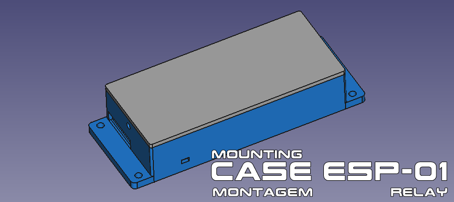
In this tutorial, you’ll learn how to assemble a custom case for the ESP-01 Relay module, with an additional compartment for a 5V power source (either a smartphone power supply board or a 100–240V AC to 5V DC converter module).
🧩 Case Components
The ESP-01 Relay case consists of a rectangular box divided into two parts, with dedicated internal compartments for the electronic modules.
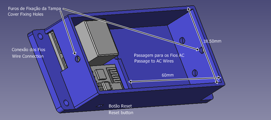
🔹 Internal Side – ESP-01 Relay Board
Length: 26.50 mm
Width: 38.50 mm
Height: 18 mm
🔹 Internal Side – Cellular Source Board (Optional) or 100–240V AC to 5V DC Converter Module
Length: 26.50 mm
Width: 60 mm
Height: 18 mm
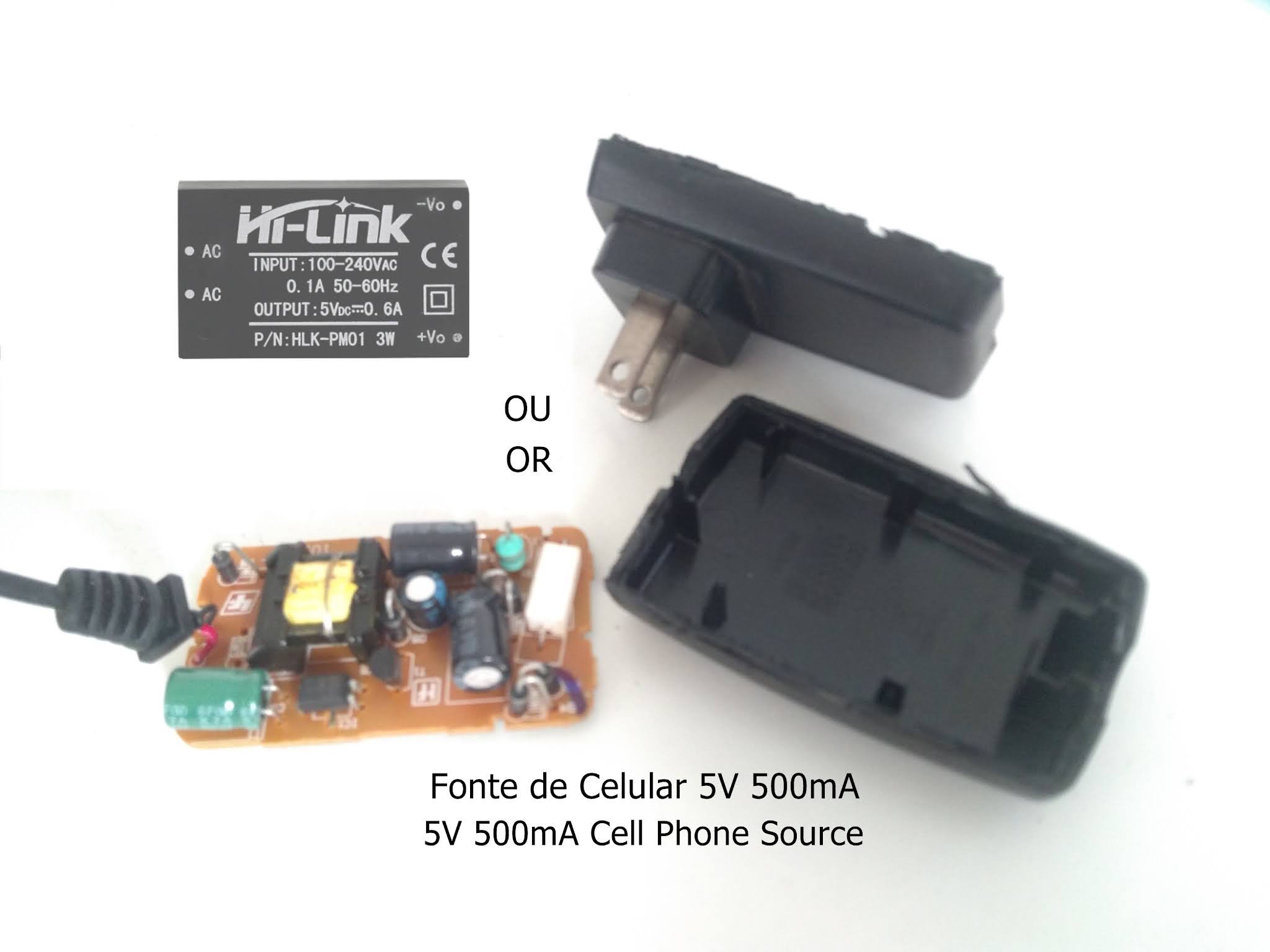
💡 Note: If you don’t have the 100–240V AC to 5V DC module, you can use the internal board of a smartphone power supply, as long as it meets the following requirements:
Voltage: 5V
Current: ≥ 250mA
🔩 Fixation
The case includes 2 side flaps, each with 2 holes, for mounting using chiboard screws.
📐 Case External Dimensions
Length: 92.80 mm
Width: 42 mm
🔌 Required Electronic Components
✅ 01 × ESP-01 Relay
✅ 01 × ESP8266 Wi-Fi Module
✅ 01 × 100–240V AC to 5V DC Module or Cellular Source Board
✅ 02 × Wires
🛠️ Final Tips
Ensure proper insulation of power wires, especially if you’re using a modified smartphone power board, to avoid short circuits.
The case is designed to provide both ease of assembly and protection for your components.
Recommended for 3D printing using PLA or ABS materials.